The Mystery of the Iron Bridge
BBC Time Watch
October 2001, shown early 2002.
Contact us01484 428203Background
Ironbridge at Telford was designed by Abraham Darby. The challenge was to see if the main ribs and pillars of the bridge may have been erected as per the Painting by Elias Marten 1779.
There is no other known documented evidence, pictorial or otherwise on how the bridge was assembled apart from this painting which suggests the use of derricks and cross members.
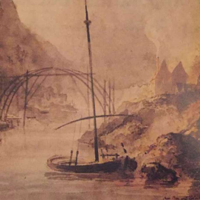
Painting by Elias Marten 1779
The intention is to cast and erect three half-size sections of ribs and uprights using only 18th Century techniques.
Green : Main ribs made in two pieces
Orange: Upright pillars
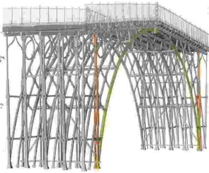
Parts to be assembled.
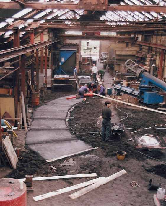
Production of the ribs
Firstly a base was laid down to cover the area of two of the ribs. The white bar coming from centre RHS is the radial pole for positioning the pattern equipment. The red pieces among the men are the pieces of patterns used. Segments of the rib were rammed with sand and then moved to form the next section of the mould.
The mould was 36 feet long with a cross section of the rib being 4.5" x 3".
The blue machine above the radial pole is the sand mixer. This mixer is computer controlled to allow resins and catalysts to be mixed with reclaimed sand. The temperature of the sand, ambient temperature and speed at which we require it to set are controlled automatically. The sand it produces is used to make the mould, into which we will pour the molten iron. It was imperative to have a flat bed as the iron like water would find its own level, if we were too high at one end the metal would overflow at the other and provide the BBC with a floor of metal.
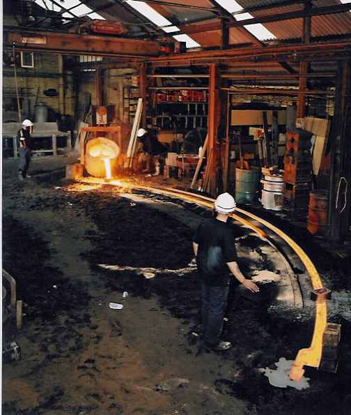
Rib moulding
The second rib is being cast at the far end and the metal can be seen half way along the mould heading towards us. The first casting was freezing as the metal reached the end. For the second cast, the metal was poured into the mould faster which allowed the metal to remain hot as it reached the far end, but this faster pouring created its own turbulence as waves ran from one end to the other and back again threatening to come over the top of the mould. As the waves were about 25mm high we had to stop the pouring and then continue as the waves subsided to a safe level.
Rib casting
The ribs seen outside before collection, the three ends show one half on the locking pieces and the bolt holes. And for the wise it also shows the shadow of the photographer.
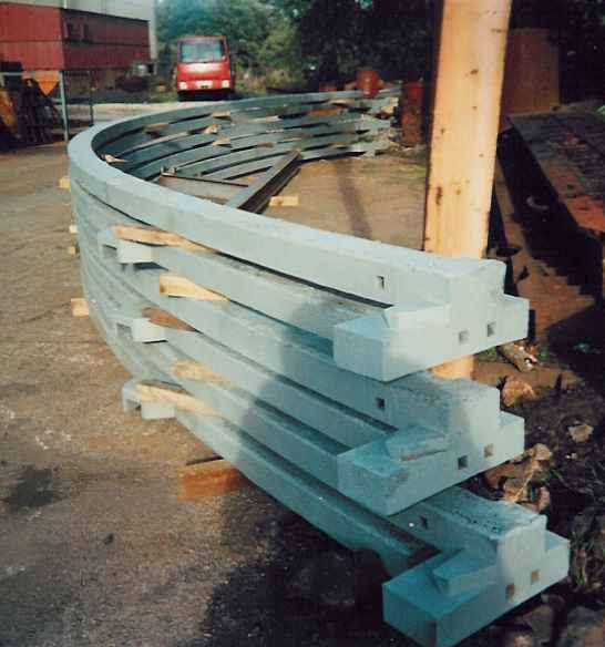
Ribs outside before collection
The ribs from the other end showing the other three locking pieces, also on the top one can be seen where the casting froze and the wave formation rippling along the top edge. The holes where the surface crust formed as the metal air cooled.
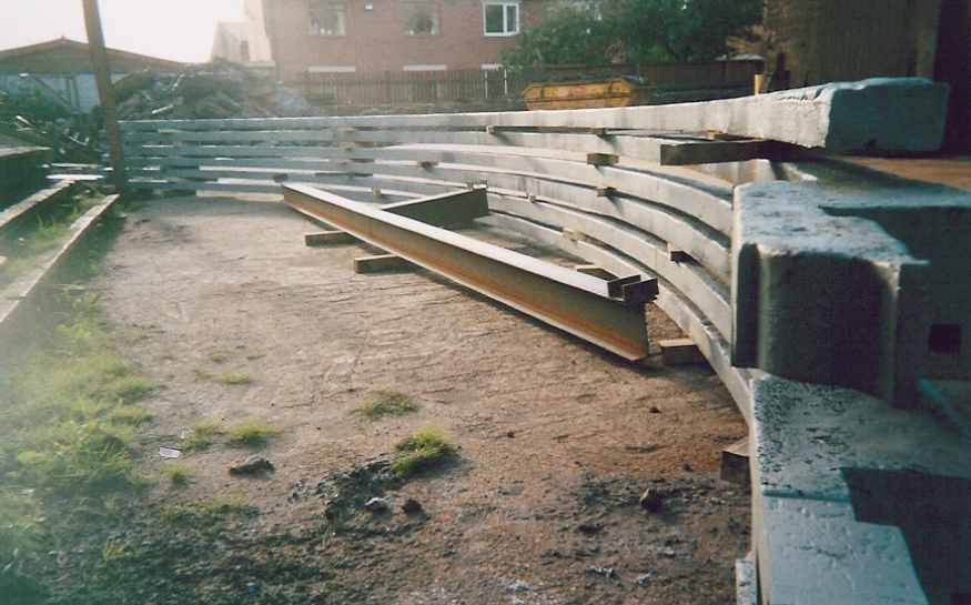
Ribs showing other three locking pieces
Production of the pillars
Open cast pouring of the pillars, the one on the right had been cast 5 minutes before. The pillars were 5m long.
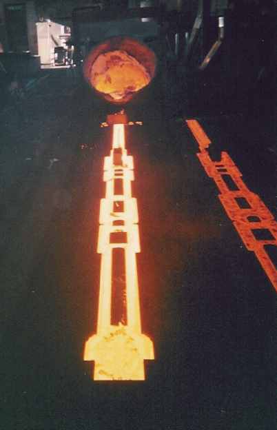
Open cast pouring of the pillars
A picture from halfway down the mould as the metal was being poured, the temperature is between 1200-1400 deg C and the flames are from any combustible material within the mould.
Halfway down the mould
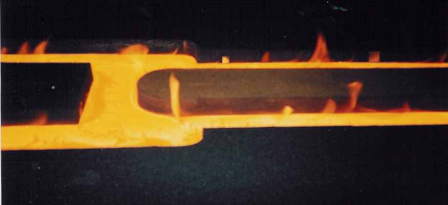
At the far end from where the casting is being poured. The foot end of the pillar receives the first of its metal that has travelled the 5m. The surface shows signs of cooling as a skin begins to form.
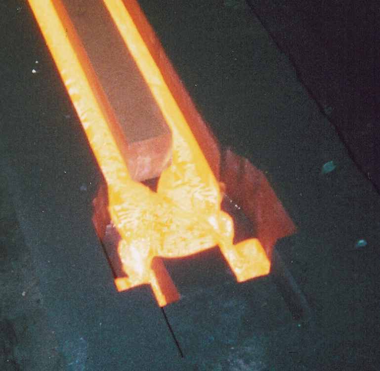
Far end where surface shows signs of cooling as a skin begins to form
Project Team
- Producer
- Deborah Perkin - BBC Wales
- Historic Adviser
- David de Haan - Ironbridge Gorge Museum
- Project Engineer
- Jamie Hillier - Buro Happold
- Erection Team
- Royal Engineers, 51 Squadron (Air Assist) Led by Lt. Ben Day
- Iron Castings
- Nigel Downs - H.Downs & Sons Ltd Huddersfield
- Ironwork Technical Drawings
- Bill Blake - English Metric Survey Team Heritage
- Structural evaluation
- Andrew Smith
- Site Management
- Alex Medhurst - Ironbridge Gorge Museum
- Abutments/site support
- Staff - Blists Hill Victorian village
Technical
Ironwork
The original ribs were cast in 2 pieces joining at the centre, each half weighing 5.75 tons. At half scale, they weigh only 15 cwt (680Kg). The span of 1 arc is 50feet (15.24m) and the chord length of each rib was 37 feet (11.3m). In the uprights holes would allow other parts of the bridge to be slotted in place.
Scaffold
The timber poles used for erection are 33 feet (10m) high, though the original scaffold poles would have stood in the river Severn and must have been nearly 70 feet (21.3m). They acted as derricks (cranes) and the frame may have been moved to a new position for each rib.
Ropes
Only hemp ropes were used to build the model, hauled by teams of soldiers. For safety, steel cables have since replaced some ropes. A trial lift of a 5 tonne weight using the scaffold, hemp ropes and pulleys required 25 people to raise it from the ground.
Abutments
The original abutments are in stone, not brick as shown here; they provide support for the base plates. Only the middle 3 base plates out of a set of 5 have been used, these are only 1" (25mm) thick, unlike the originals, which were 4" (100mm).